
language
| Overview of the XCP protocol | |||||||||||||||||||||||||||||||||||||||||||||||||||||||||||||||||||||||||||||||||||||||||||||||||||||||||||||||||||||||||||||||||||||||||||||||||||||||||||||||||||||||||||||||||||||||||||||||||||||||||||||||||||||||||||||||||||||||||||||||||||||||||||||||||||||||||||||||||||||||||||||||||||||||||||||||||||||||||||||||||||||||||||||||||||||||||||||
| Release Time:2024-01-18 | Page View:0 | |||||||||||||||||||||||||||||||||||||||||||||||||||||||||||||||||||||||||||||||||||||||||||||||||||||||||||||||||||||||||||||||||||||||||||||||||||||||||||||||||||||||||||||||||||||||||||||||||||||||||||||||||||||||||||||||||||||||||||||||||||||||||||||||||||||||||||||||||||||||||||||||||||||||||||||||||||||||||||||||||||||||||||||||||||||||||||||
|
Overview of the XCP protocol 1. Introduction to XCP Protocol 1.1. Background: With the rapid development of automotive electronics, there are more and more ECUs in cars, and various controllers work together to control different components. The ECU collects different input information, such as accelerator pedal, brake pedal, cruise control, start stop, etc., and uses specific algorithms to calculate the output. In order to achieve the desired control effect, the algorithm contains many calibratable parameters, which are adjusted according to different inputs and working conditions. The program in the ECU is designed and developed by software engineers, while the calibratable parameters in the algorithm need to be set in experiments based on our pursuit of economy, power, comfort, and compliance with emission regulations. This part of the work is determined by the calibration engineer through repeated iterations of performance analysis using modified parameters after software development, Therefore, calibration engineers need to obtain (read operation) and calibrate (write operation) different parameters.
1.2. XCP proposed: XCP, also known as Universal Calibration Protocol, is a new calibration protocol proposed by ASAM (Association for Standardization of Automation and Measuring Systems) in 2003 that can be calibrated on different communication buses. Here, X represents transmission on different transport layers (CAN, Ethernet, FlexRay, SCI, SPI, USB). I am currently using version 1.3, which was updated in 2015. XCP is mainly used for measuring and calibrating internal parameters of ECU. This protocol can synchronize data collection with tasks and interrupts running within the ECU, ensuring that the required parameter values can be quickly collected whenever the ECU software updates parameters.
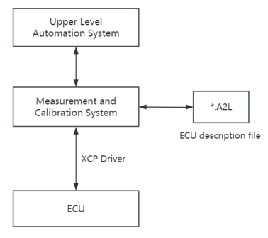
2. A2L file introduction In order to achieve the measurement and calibration function of the internal parameters of the ECU, the XCP Master must be aware of the detailed information of different memory areas of the ECU. The ASAP2 (A2L) file is a description file for the ECU, and XCP is always used in conjunction with the A2L file. This file contains the necessary information required to use XCP, including detailed address information about ECU parameters, memory variables, and ECU memory, as well as security information on how to unlock access to XCP functions. A2L is generated based on ECU software, and the objects of ECU software are included in the A2L file. Figure 1 shows the interface model between measurement and calibration tools and ECU, A2L files, and higher-level automation systems.
Figure 1: The Interface Model of ASAM
3. XCP on CAN Reading and Writing Practice Practice mainly involves using a CAN box to communicate with the ECU and perform data read and write operations based on the A2L file description. 3.1. XCP on CAN message introduction: The information framework of XCP on CAN is shown in the table below. The defined PID has corresponding XCP instructions from C0 to FF. After receiving the instructions, the slave returns the result from FC to FF based on the response situation. The CAN message has a total of 8 bytes, and the XCP header is empty, starting with PID, which is the instruction from C0 to FF. The corresponding message returned by the slave also starts with PID.
3.2. Reading and writing practice 3.2.1. Connect Firstly, it is necessary to establish a connection between the master and slave devices. The format of the host message is as follows:
The format of the slave return message is as follows:
The explanation of Resource is shown in the table below:
The explanation of Com_mode is shown in the table below:
The following is an explanation of the message content based on practical examples: Example: TX FF 00 RX FF 1D C0 08 00 01 01 FF is the connection command; Mode 00 indicates that the host can communicate with the slave to start XCP FF indicates successful connection; 1D stands for 0001 1101, indicating that all resources are available; C0 stands for 11 million, indicating a communication mode that supports additional information of different types. The slave block mode is available, and AG is BYTE; 08 indicates that the maximum byte of CTO is 8; 0800 indicates that the maximum byte of DTO is 8; Two 01s represent the protocol layer and transport layer versions.
3.2.2. Get Status After the master-slave device completes the connection, it needs to obtain the current status. The format of the host message is as follows:
The format of the slave return message is as follows:
The explanation of Session is shown in the table below:
The explanation of Protection is shown in the table below:
The following is an explanation of the message content based on practical examples: Example: TX FD RX FF 00 00 00 00 00 The 00 in the second byte of RX indicates that all resources are available; If the second byte is 1D, which is 0001 1101, it means that all resources are not locked and an unlock operation needs to be performed before using the corresponding command.
3.2.3. Unlock When the desired resource is locked, decryption should be performed first. The key is obtained through seed transformation. First, you need to obtain the seed. The format of the host message is as follows:
The format of the slave return message is as follows:
The following is an explanation of the message content based on practical examples: Example: TX F8 00 01 RX FF 0A A7 88 5F D3 C3 58 TX F8 01 01 RX FF 04 EF 28 34 EF The 00 in the second byte of TX indicates obtaining the first part of the seed; The third byte is 01, indicating that the target to be unlocked is CAL/PAG. The second byte 0A of RX represents the seed length, which is 10, but only the first 6 bytes can be obtained first. Then use the F8 command again, select 01 as the mode to retrieve the remaining seeds, and the second slave will return the remaining 4 bytes.
After obtaining the seed, the key is obtained through transformation, and then the decryption operation is carried out. The format of the host message is as follows:
The format of the slave return message is as follows:
The following is an explanation of the message content based on practical examples: Example: TX F7 09 82 FC 3F 43 50 D2 RX FF 1D TX F8 03 3B 00 86 RX FF 1C Similar to obtaining seeds, when the key length is greater than 6 bytes, it needs to be sent multiple times. In this example, the key length is 9, so the first input is 6 bytes, and the second input is the remaining 3 bytes. Finally, the slave returned 1C, which is 0001 1100, indicating that CAL/PAG resources are available and unlocked successfully.
3.2.4. Data Reading After successful unlocking, data reading can proceed. The format of the host message is as follows:
The format of the slave return message is as follows:
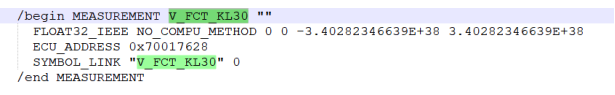
The following is an explanation of the message content based on practical examples: Example: TX F4 04 00 00 28 76 01 70 RX FF D7 A3 3C 41 In this example, the reading is the power supply voltage value. Retrieve V_ FCT_ KL30 fields in A2L file , as shown in Figure 2. KL30 is a battery with a power supply voltage of 12V, and the theoretical reading should be around 12V.
Figure 2: Description of V_ FCT_ KL30 in A2L file From the A2L file, it can be obtained that the data type is floating-point number and the data address is 0x70017628. Attention should be paid to the order of high and low addresses here. In the CAN message, the address should be written 28 first and 70 last. Similarly, when returning data values from the slave, attention should also be paid to the order of high and low bits. Convert 413CA3D7 to a floating-point number of 11.79, which is close to the theoretical value.
3.2.5. Data calibration The process of data calibration is as follows: first, set the data calibration page, then set the address, and finally write the data to that address. Data calibration page settings: The format of the host message is as follows:
The format of the slave return message is as follows:
Address settings: The format of the host message is as follows:
The format of the slave return message is as follows:
Data calibration: The format of the host message is as follows:
The format of the slave return message is as follows:
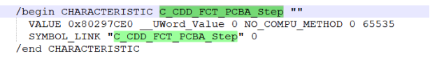
The following is an explanation of the message content based on practical examples: Example: TX EB 83 01 01 RX FF TX F6 00 00 00 E0 7C 29 80 RX FF TX F0 02 01 0D RX FF The second byte of the page setting command is written as 83, which is 1000 0011, indicating that all modes are enabled, or only one or a few of them can be enabled, such as writing 01, 02, 80, etc. In this example, C_CDD_FCT_PCBA_Step was calibrated and retrieved from the A2L file, as shown in Figure 3:
Figure 3: Description of C_CDD_FCT_PCBA_Step in A2L file The address of C_CDD_FCT_PCBA_Step can be obtained from the A2L file, and can be set using the F6 command. It is also necessary to pay attention to the high and low order of the addresses. Calibrate it to 0x0D01 and use the F0 command for calibration, also paying attention to the order of high and low positions. After calibration is completed, you can use the F4 command to read and verify if the calibration is successful.
4. XCP Protocol Summary The XCP protocol is an open standard widely used for communication between multiple automotive system and tool providers. The XCP protocol uses an efficient data transmission mechanism, providing flexible data access and control functions. It is possible to monitor and modify the internal parameters of the ECU in real-time, and also supports offline calibration, allowing for parameter adjustment and configuration while the vehicle is offline. In addition, the XCP protocol supports secure authentication and data encryption, ensuring data security during communication. The XCP protocol has advantages and characteristics such as cross platform compatibility, efficiency, flexibility, and safety in automotive system applications, providing a reliable solution for the measurement and calibration of automotive electronic systems.
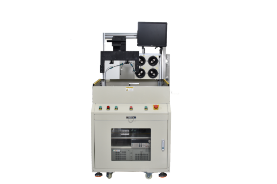
5. Future development direction and FineTooling solutions With the continuous development of automotive intelligence, the electronic systems of vehicles have become increasingly complex. Based on the XCP protocol, the process of reading and writing internal data of the ECU using the CAN box has ended. In addition to paying attention to the technical details mentioned above, this method's work efficiency will also become a constraint on the upgrading and development of automobiles in the future. The traditional automotive E/E architecture adopts a distributed approach, and the core of the functional system depends on the accumulation of ECU and sensor quantities. With the acceleration of intelligent upgrading of automobiles, the original distributed architecture is facing problems such as a sharp increase in research and production costs, reduced safety, and insufficient computing power. NEV first began to centralize the E/E architecture, integrating originally isolated ECUs with each other, and domain controllers emerged as a result. The trend of automotive intelligence and OTA demand has driven the transformation of automotive E/E architecture from distributed ECU architecture to domain controller solutions. In the future, intelligent vehicles will move towards sustainable upgrading, and vehicle manufacturers will choose a "hardware over configuration, subsequent software iteration and upgrading" approach to enter the era of truly software defined cars. The domain controller is the "brain" of future automobiles. In order to meet higher level intelligent driving needs, the main control chip in the domain controller will move towards heterogeneous SoC that integrate "CPU+XPU" (XPU includes GPU/FPGA/ASIC, etc.). For the convenience of iterative upgrades, the measurement of data in domain controllers is particularly important. The XCP protocol provides an efficient and flexible measurement and calibration communication mechanism. It can meet the demand for real-time monitoring and modification of internal parameters of vehicles. But if traditional methods continue to be used for data measurement, its efficiency will also become a resistance factor for the upgrading and development of intelligent vehicles. Finetooling combines the advantages of the XCP protocol to provide XPCU automated measurement machines for the efficiency of internal data measurement in ECU or domain controllers, which can help customers quickly collect and analyze internal data in ECU or domain controllers. By greatly improving efficiency through automated measurement, we can assist in the upgrading and development of intelligent vehicles.
Figure 4: FineTooling XPCU Automatic Testing Machine |
|||||||||||||||||||||||||||||||||||||||||||||||||||||||||||||||||||||||||||||||||||||||||||||||||||||||||||||||||||||||||||||||||||||||||||||||||||||||||||||||||||||||||||||||||||||||||||||||||||||||||||||||||||||||||||||||||||||||||||||||||||||||||||||||||||||||||||||||||||||||||||||||||||||||||||||||||||||||||||||||||||||||||||||||||||||||||||||
| Prev:Vibration State Monitoring Based on Accelerometer Next:Fidas data acquisition chassis: current and voltage data acquisition solutions |
|||||||||||||||||||||||||||||||||||||||||||||||||||||||||||||||||||||||||||||||||||||||||||||||||||||||||||||||||||||||||||||||||||||||||||||||||||||||||||||||||||||||||||||||||||||||||||||||||||||||||||||||||||||||||||||||||||||||||||||||||||||||||||||||||||||||||||||||||||||||||||||||||||||||||||||||||||||||||||||||||||||||||||||||||||||||||||||
Tel:020-82108945-2003
Fax:020-82108945-2001
Email:Marketing@finetooling.com
Add:D306, No.1, Nanxiang Branch Road, Science City, Guangzhou City

Official Wechat Accounts
Industrial Product Customization
Copyright © 2020 广州市方瞳科技有限责任公司All Rights Reserved 备:粤ICP备16102240号
Official Wechat Accounts